Search Results for ‘Processing’
After more than two years of improving and honing my own project, and checking the competition I got the urge to share some of my thoughts on what makes or breaks a PETSCII editor. A lot of this stuff is actually pretty self-evident in the end, but it has taken hours and hours to figure it out. Bear with me 🙂
Not pixels
When comparing a PETSCII editor to a generic paint program there are plenty of similarities, but also notable differences. Instead of tens of thousands of individual pixels we’re dealing with a relatively low-resolution grid consisting of predefined symbols. On the one hand it is easier to deal with text, since tools such as lines, ellipses and curves are rather useless, but on the other hand there is a constant need to effectively choose and alternate between the available symbols, which requires different kind of thinking altogether. In other words, adopting tried and tested methods from paint programs alone will not lead to optimal outcome.
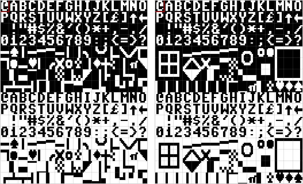
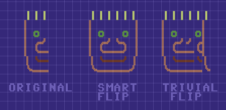
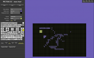
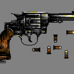
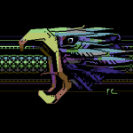
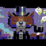
Among the most powerful features of PETSCII (the editor) are smart rotation and flipping of a selected area which take into account the form of the character. I take no credit for these, as it was Tero who came up with the idea in the first place and wrote the remapping tables. Not every character can be rotated or flipped, but even so you’ll save a lot of time when working with symmetric forms. See the following image for an example of how “smart” flipping works as opposed to simply moving the characters:
Typing vs. drawing
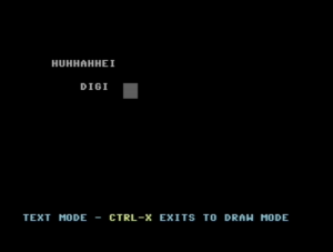
In essence there are two main methods to get characters on the screen. The traditional way, typing, was initially the only possible option and is still heavily present in modern-day editors (for example AAE). A mouse is something of a rarity on C-64s and graphical symbols can be conveniently found on the keys, so on a real machine typing makes all sense – but a lot less so on your PC or Mac which has a different keyboard to begin with.
I’ve included a half-assed typing mode in PETSCII, mostly for the sake of actually writing text, even though all the symbols can be typed too if it’s really necessary. In any case, drawing with a mouse was the preferred metaphor right from the beginning. There are pros and cons to both, but using a mouse definitely makes it quicker to sketch forms in the spirit of direct manipulation. A little but important detail is to show the character before it is actually placed: otherwise you end up constantly undoing the operation.
Character selection
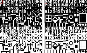
When drawing, a great deal of time is spent on selecting the next character. The first thing to do was to reorganize the otherwise messy character set to group related symbols together (thanks go to Tero again). Jambonbill went even further and repeated the same characters multiple times to create visually continuous groups.
A well-organized character selector is a good start, but much more can be done to facilitate an efficient workflow. For example in PETSCII the aforementioned rotate and flip operations work with individual characters as well: press a single key and get the next corner for a window or a box. In the same lines I came up with “smart sets”, predefined sets that you can walk through with a keypress. Another little bit that arose from a real need was to let the user quickly shift stick characters (used for various lines) right/left/up/down.
As a piece of PETSCII art is drawn, you typically start accumulating useful characters and their combinations in the image itself. Instead of always going for the selector – which in Playscii even occludes part of the canvas – it makes sense to quickly pick a character from the surroundings.
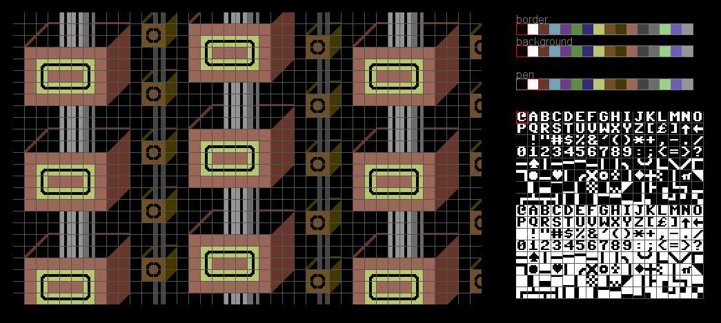
Grid
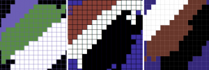
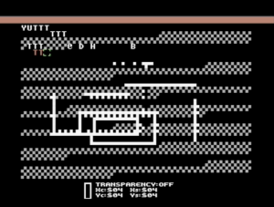
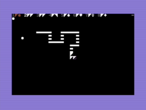
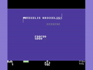
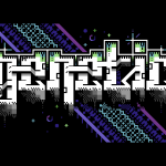
You can get away without a grid if the images are comparably small, but all in all a well-working grid can be of great benefit when selecting regions and aligning symbols with each other. After at least three complete rewrites of the drawing code I’ve eventually come up with the following findings:
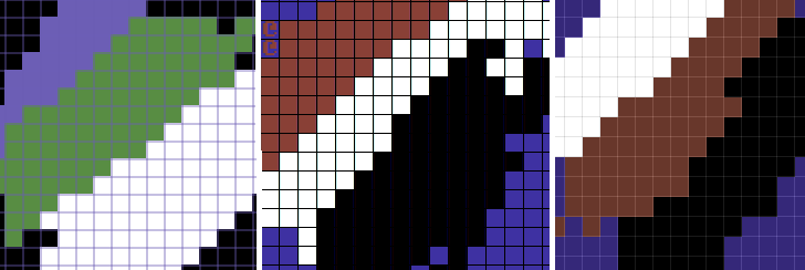
- Don’t make the grid intrusive (thick, contrasty etc.)
- No single color works for the grid alone. Instead, darken light colors and lighten dark colors to keep it harmonious.
- It’s useful to have a quick on/off toggle
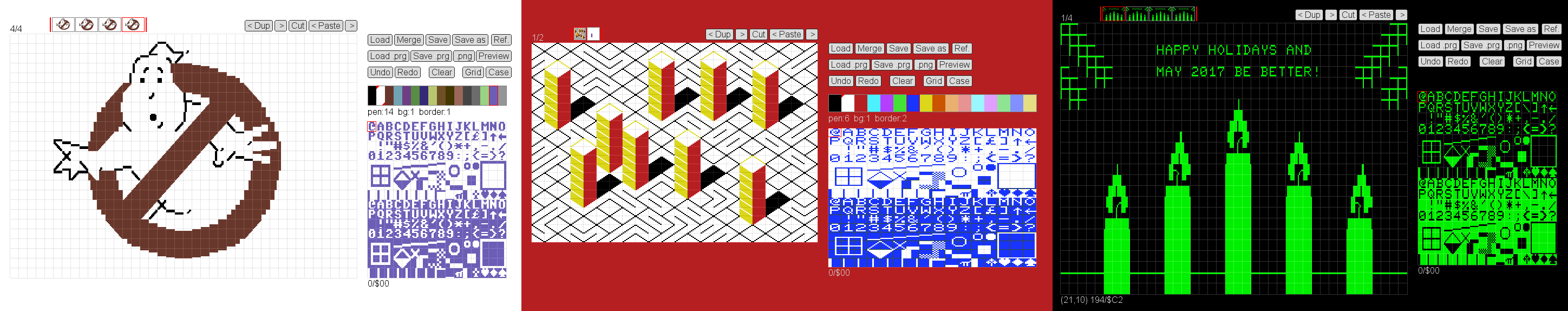
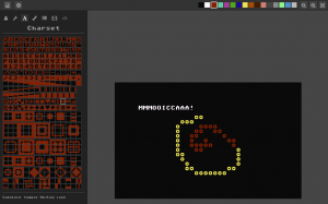
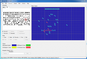
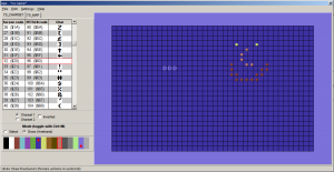
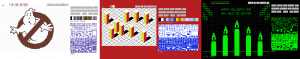
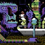
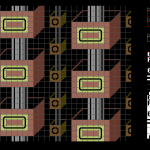
Below a few real-life examples of how the grid looks like in different editors.
File formats
The file formats supported by an editor tend to reveal its intended use. Some editors are clearly geared toward actual machines, stick to their limitations and facilitate easy exporting to formats like .prg, which can be run on real hardware. At the other end of the spectrum you might get only PNG files or GIF animations out for easy distribution on the web.
I’ve been balancing between the two extremes myself: initially the idea was to support software development and participate in demoscene competitions. However, it soon became evident that many people needed and wanted to distribute their works online for easy viewing, so I had to give in and add a PNG exporter. Supporting multiple exporters for multiple machines obviously means plenty of error-prone extra work.
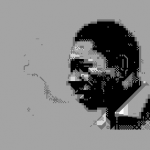
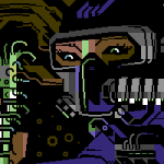
Automatically converting existing images to PETSCII is a different discussion altogether. Having said that, many users would welcome such a feature for, say, converting their self-portrait into retro character art. In addition, an artist can benefit from a reference image, as some of them prefer sketching on paper first before firing up the actual editor.
Animation and other fancy features
Creating proper support for animation is probably as big a task as all the others combined. As of now there are animation features in multiple editors, but none of them really go beyond simple copy/paste and playback of the frames. Think of a proper video or animation editor to realize how many possible features there could be.
Undo and redo aren’t exactly “fancy” features from a user perspective, but it takes some effort to include them in your editor. It’s definitely a good idea to implement them early on, as adding them as an afterthought might prove painful – speaking from experience 🙂 There are more and less sophisticated ways to go about undo, but as we’re dealing with quite little data it’s not all that bad to just save the buffers between operations for undoing or repeating the steps. Another welcome safety network comes in the form of automated backups.
There are a couple of editors that support layers, approximately in the lines of your familiar photo editing software. I can definitely see some uses for them, for example for separating the background from foreground figures. Then again, to fully support layers requires considerable effort, and they aren’t quite as useful as in photo editing, as you can’t really have things like translucency or color manipulation.
Accessibility
While some users are after a genuine user experience – tapping away on a real C-64 – most seem to welcome the ease of cross-development. Supporting the three main desktop platforms (plus their different flavors) is tedious at best, and thus some of the editors run on Windows only. Being a Mac/Linux user myself this was, of course, out of the question, but luckily Processing lets you export multiplatform applications with little extra effort. On the downside, Java is required on the target machine, which will turn off some possible users (and rightfully so).
As I see it, the best bet these days would be to develop for the web. In spite of the possible troubles with browser compatibility, web applications tend to be multiplatform by nature. In addition, you don’t need to go through the trouble of installing anything on the local computer. If I were to start from scratch, I’d probably take this route. As of now there are two online editors already, even if neither of them is quite complete yet (see my previous post).
Another angle to accessibility follows from the fact that people use laptops and tablets with a crammed keyboard. Therefore, relying on numpad or function keys beyond F10 is obviously out. Likewise, touch pads (esp. Apple ones) might not have more than one or two mouse buttons available, which requires some thought. Even more so for touch screens, which again introduce a new set of challenges.
Documentation
I can wholeheartedly relate to programmers that want to spend their free time on interesting coding problems instead of writing documentation. Even if it’s not exactly fun, there is a need for at least some product support: be it a manual, online help or a website. A few nice example works done with the editor definitely don’t hurt, as they show what’s possible and spark user interest.
Conclusion
Cross-development tools for PETSCII are a surprisingly new phenomenon. As far as I know, they’ve been around for not much more than five years, after which things have really started picking up speed. The threshold of starting to do character art has probably never been lower, and new authors are popping up every now and then.
All in all, the challenge of programming a PETSCII editor is twofold: there’s the tech and then there are the users. It’s not hard to put together basic minimum functionality, but going beyond that has turned out so laborious that most projects have been abandoned shortly after their initial release. PETSCII too would require quite an overhaul by now to accommodate any new major features – feature requests are, of course, neverending.
Implementing new modes, tools and so on is one thing, but thinking about the workflow and making the features useful is another. If you’re not much of an artist yourself, it’s at least good to have one in the loop: user feedback or even going so far as to observe someone’s work over their shoulder provide valuable insight and motivation. Ok ok, that was the design teacher in me speaking 🙂
April 6th, 2016
I’ve been rather actively involved with PETSCII art for the last couple of years, coding, drawing and even conducting a bit of research. As PETSCII is kinda fashionable now, and many people would like to experiment with it, here’s a little overview of the available editors and their pros and cons. The list aims to be complete, so if there’s anything missing, let me know. Let’s start with native tools and then move on to cross-development.
It’s a fine line, but I’ve decidedly excluded various text editors that could be used for character graphics as well.
Digital Paint 4.0 (C-64, link)
Probably ok for its time – can’t quite pinpoint when exactly it was released. In addition to the original version coded by Aaron Hightower there are various hacks by sceners who added missing features. In addition to typing, you can paint filled boxes and edit colors.
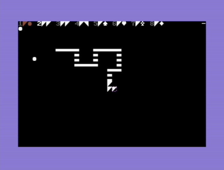
TBoard-Painter 1.1 Pro (C-64, link)
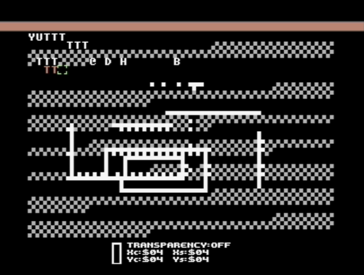
Another oldie, this time by Tao/Triad. The most notable extra feature is the 1/4 char pseudographics drawing mode. The image can be larger than the screen size, which together with the name suggests it was meant for BBS graphics. As a nice little touch the x/y location display uses hex numbers 🙂
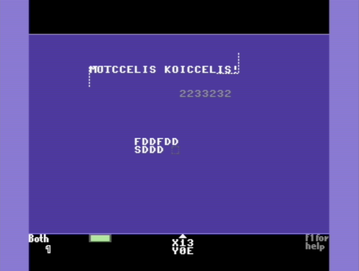
Tyronpaint 2.1 (C-64, link)
Not much new to say about this: you can type text, change the color or draw blocky 1/4 dots. The images can be higher than 25 lines. Created by Lynchbit/Alpha Flight in 1996, this improved version is from 2006.

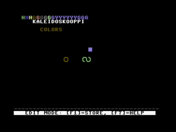
Kaleidoscope 4.0 (C-64, link)
Very simple, but at the same time easily comprehensible editor by BroBryce64 all the way from 1989. Not many features there, but you can type chars and change colors. A curious extra is the “rainbow mode” which cycles the colors after each character.

PETSCII Paint 0.5 (C-64, link)
A rudimentary tool by 0xDB from 2011. The basics do work: you can select characters, change colors and save the outcome, but even simple things tend to be on the tedious side.
Petscii Editor 4.6 (C-64, link)
FieserWolf’s editor is undoubtedly the most popular one when it comes to programs running on real hardware. As the version number suggests, there have been plenty of iterations and the workflow has been improved a lot since the initial releases. Once you get used to the UI, there’s useful functionality such as copy/paste, recoloring and multiple pages available. Several notable works have been produced with this editor.
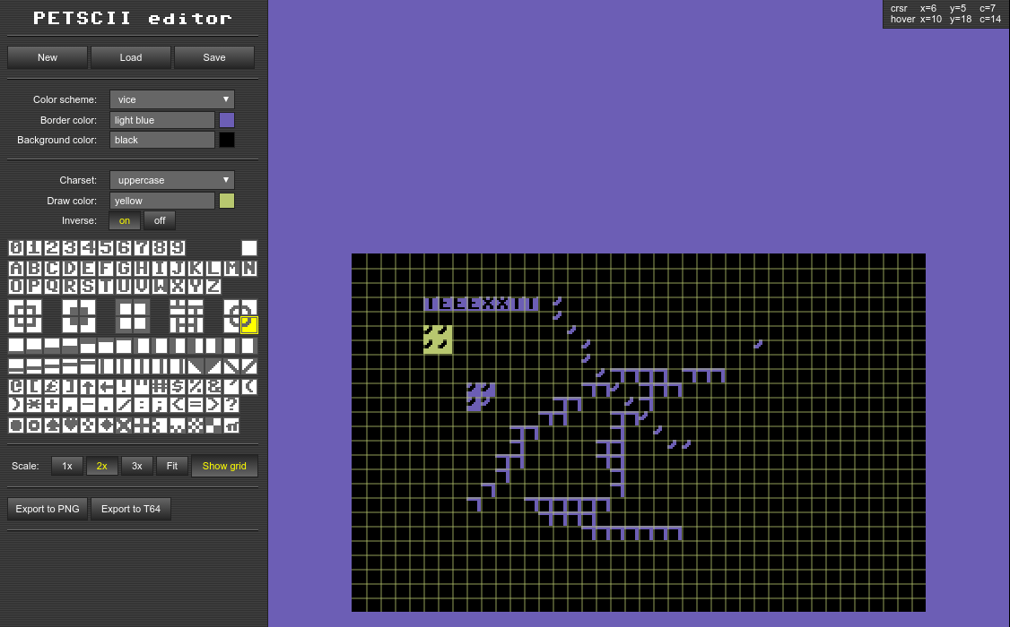
Online PETSCII Editor (online, link)
A web-based solution by Krissz from 2013. I like the idea that you can draw on a normal browser without installing any software or digging the old warhorse from the closet, but this particular project seems to have been abandoned. You can both draw and type, and the character selector is well though out. On the other hand, there is little functionality to support advanced editing.
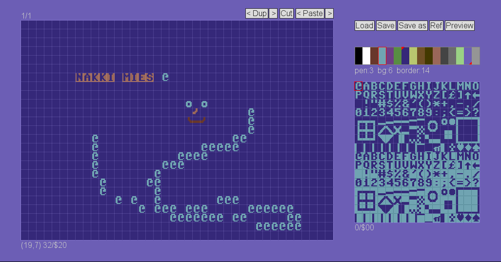
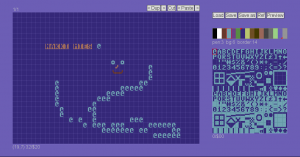
PET Shop Pro (online, link)
As of now there’s very little documentation on this editor by Jambonbill, as it is still work in progress and not officially released. Nevertheless, quite a promising online tool which lets you even do animations. Originally based on Krissz’s editor (see above), but was mostly rewritten after that. The character selector is well designed, you can edit images of various sizes plus export them to different formats, and even script the editor. There are still some bugs around, which will hopefully be ironed out at some point.
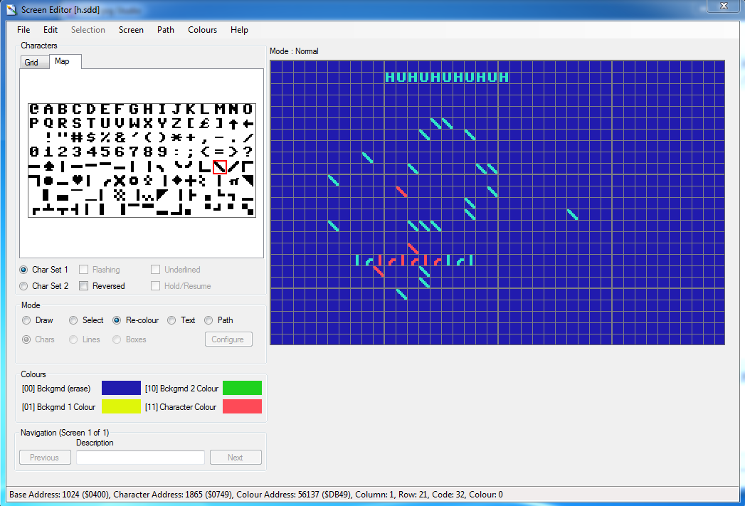
CBM .prg Studio (Windows, link)
Arthur Jordison’s CBM .prg Studio is a complete development environment that lets you create software for the Commodore 8-bits. One of its parts is the screen editor, which is actually quite usable for artistic endeavours too. Largely served as the source of inspiration for the editor below.
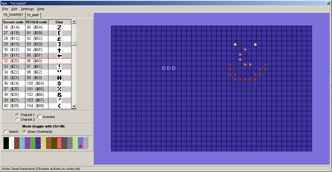
APE (Windows, link)
APE (Another Petscii Editor) by MrXaliasH from 2013 is Windows-only, but does run fine under Wine as well. The basic functionality (drawing, color selection, copy/paste and even undo) is there, but it seems the project was quickly dropped after its initial release.
C64 AAE (Windows, link)
C64 ASCII Art Editor by RADSoft hails from Poland. Windows-only, but runs somewhat ok under Wine except the color editor. Apparently the development ceased in 2012, but in spite of that there are some unique features – most notably layers, which were a firstie in the scene. The animation features are also among the most advanced. Drawing happens by writing, but unfortunately the key mapping doesn’t suit all keyboards. Furthermore, keyboard shortcuts require quite heavy juggling with various ctrl/shift/alt combinations.
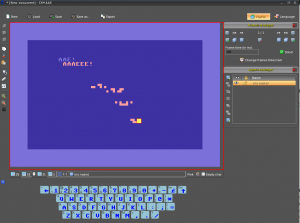
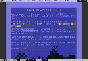
EDSCII and Playscii (multiplatform, link)
EDSCII by JP “Vectorpoem” LeBreton was one of the first editors I tried in 2013. Later on its development halted and Vectorpoem created a new tool called Playscii. Both versions focus on PETSCII-like retro graphics instead of sticking to the exact capabilities of the C-64. Still under development, Playscii already features plenty of functionality such as different character sets, layers, animation frames and smooth zoom, plus of course the standard editing tools. There is also something called “game mode”, which I didn’t quite understand at first sight, though.
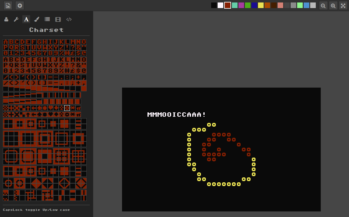
PETSCII (multiplatform, link)
Do not expect me to be very objective with this 🙂 The project, initially coined by me and Dr. TerrorZ, started in 2013 and has received occasional updates ever since. In addition to the standard stuff there’s rudimentary support for animation and other machines than just the C-64 (VIC-20, PET and Plus/4). One recognized problem is that because of Processing, the program runs on Java, which spells trouble these days. The GUI is undeniably “no-nonsense” with most functions hidden behind single-key shortcuts.
In conclusion, there’s already quite a variety of tools available these days, and some are surely still missing from the list – not everyone has made their software public in the first place. At one end of the spectrum there are hardcore editors running on genuine hardware, and at the other retro art oriented tools aimed at recreating the old look with less regard for authenticity (at times called fakescii). Pick your poison!
edit: More additions, thanks to Goto80 for the tips!
edit2: More details on Pet Shop Pro received from Jambonbill himself.
March 22nd, 2016
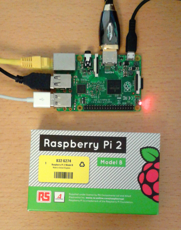
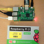
Lägään tällä hetkellä näiden Raspien kanssa hieman perässä, sillä rupesin vasta testailemaan synttärilahjaksi saamaani 2B-mallia. Jälleen kerran hieman nopeampi kolmonenhan tuli juuri uunista ulos.
Juhlapuheista huolimatta etenkään alkupään Raspeista ei todellakaan ollut työpöytäkäyttöön: muistia oli liian vähän, X:n ja SDL:n kiihdytykset riittämättömiä, ja jo muutenkin hitaan koneen hyydytti viimeistään käyttiksen ajaminen SD-kortilta. Muutaman vuoden aikana ytimiä on tullut kolme lisää, ja kenties vielä tärkeämpänä parannuksena muistin määrä on noussut gigatavuun. Mutta ollaanko vieläkään työpöytäkäyttöön riittävällä tasolla?
Kyllä, ei ja ehkä. Raspi 1:een verrattuna työpöytä pyörii mainiosti, mutta toisaalta hitainkin nykypäivän Intel-pohjainen miniläppäri on edelleen nopeampi. Hitaus ja nopeus ovat pitkälti ohjelmista kiinni: mukana seuraava Web-selain ja LibreOffice ovat aivan käyttökelpoisia, kun taas Java-pohjainen Processing hyytyi varsin ikävästi. Pikaisesti kokeilemani kevyet emulaattorit toimivat sinänsä ok X:n päällä, mutta kiinteän resoluution ja puuttuvan video-overlayn vuoksi niitä ei saanut koko näytölle (resoa voisi toki pudottaa, mutta se on ongelman kiertämistä eikä ratkaisua).
Pahin pullonkaula tuntuu edelleen olevan massamuisti. Siinä missä SSD:istä on tullut päivittäistavaraa isojen koneiden puolella, pikkulaudoissa ollaan edelleen jumissa USB2:n ja muistikorttien maailmassa. Odroideissa nähty eMMC on jonkin verran parempi, mutta jää sittenkin SSD:lle mennen tullen.
Parhaimmillaan Raspit ovat niille erityisesti räätälöityjen softien kanssa: mediatoistimista, emulaattoreista ynnä muista on optimoituja versioita, jotka käyttävät videoskaalaajaa tai OpenGL ES:ää tavanomaisten kirjastojen sijaan. Yllätyin itsekin, kuinka paljon 3D-rauta jaksoi puskea, kun sitä ohjelmoi järkevästi. Ylimääräiset kerrokset, kuten Java ja JavaScript, ovat puolestaan myrkkyä suorituskyvylle.
Monia päivittäisiä asioita voi tehdä jo nykyiselläänkin riittävän sujuvasti, kunhan hyväksyy tietyn ajoittaisen tahmailun. Ainoaksi peeseen korvaajaksi en Raspia edelleenkään laittaisi, enkä usko kolmosenkaan tilannetta merkittävästi muuttavan, varsinkin kun massamuistiväylät eivät ole sen nopeammat. Toisaalta tarkkaan rajatussa yksittäisessä käytössä etenkin tämä uusi Rapsutin voi olla aivan riittävän tehokas ja hinnaltaan kymmenesosa “oikeasta” tietokoneesta. Palataan asiaan taas parin sukupolven päästä.
February 29th, 2016
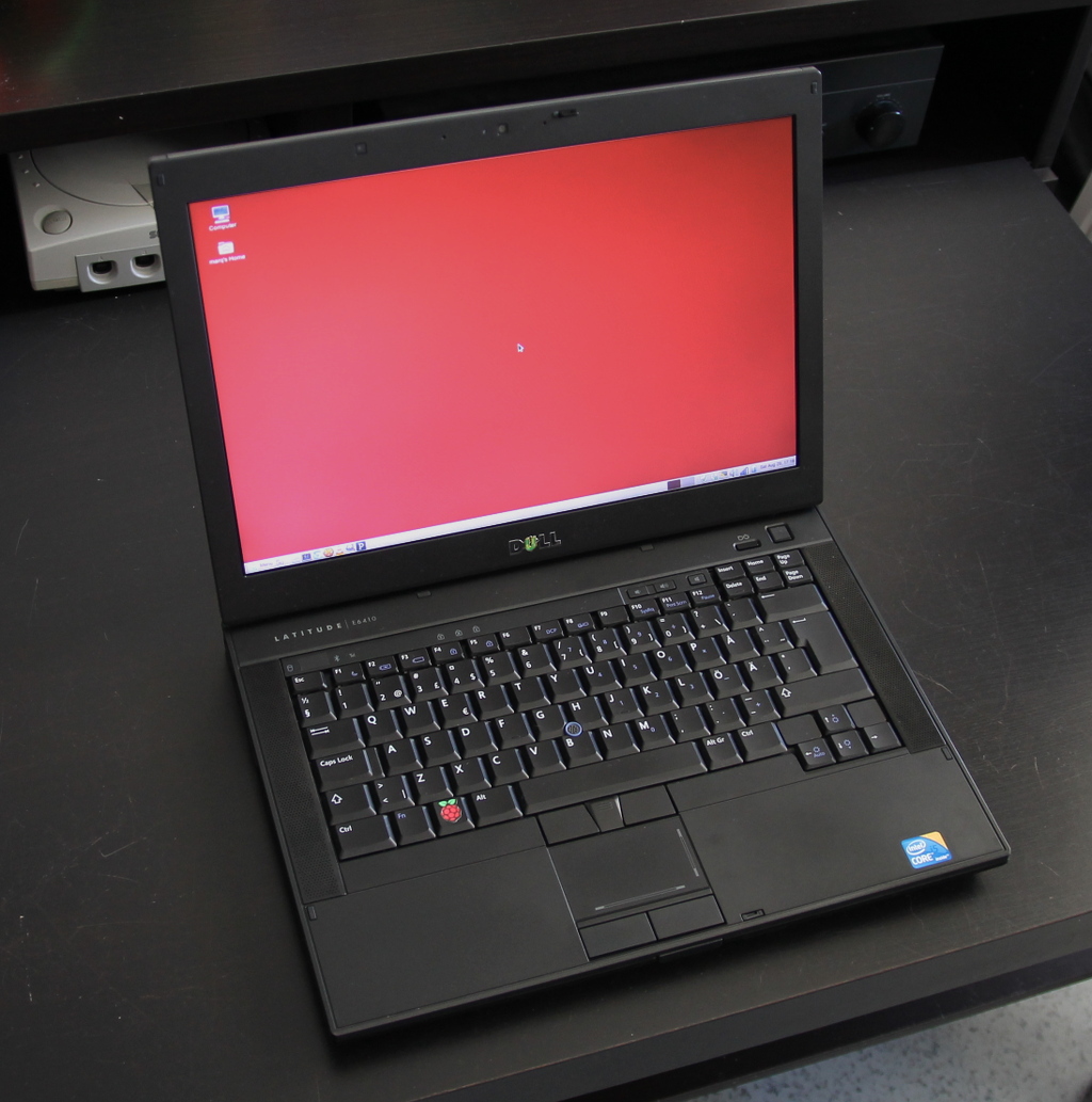
Kiitos nimettömän lahjoittajan, sain käsiini kolme käytöstä poistettua, muutaman vuoden ikäistä Dellin bisnesläppäriä, joista kaksi siirtyi jo eteenpäinkin. Kaksi niistä oli mallia E4310 ja viimeisenä trokattu E6410. Kaikissa oli edelleen ihan ajanmukainen i5-prosessori – oikeastaan vain pienet kiintarit, kuolleet akut ja nykymittapuulla vaatimattomat näytöt kertoivat koneiden iästä. Yhteen meni lopulta Windows 7 ja kahteen tietysti tuttu Mint/Mate.
Takavuosina Linux+kannettava oli huono yhdistelmä monestakin syystä: eksoottisille näytönohjaimille ja wlan-piireille ei ollut tukea, virransäästöominaisuudet olivat puutteellisia ja sleeppi toimi, jos toimi. Noista ajoista on kuitenkin tultu ilmeisen kauas, sillä Mint meni heittämällä ineen kaikkiin koneisiin niin 32- kuin 64-bittisenäkin versiona. E6410 kaatuili uhkaavasti asennuksessa, mutta syypääksi paljastuivat hankkimani uudet 1,5 V muistit (blääh!). Olisi pitänyt olla 1,35 V kampoja, mutta onneksi väärät kelpasivat edes Chromebookiin, joka puolestaan luovutti kaksi gigaa takaisinpäin.
En uskaltanut odottaa ihan liikoja, mutta hyvinhän se meni. Kaikki toimii suorilta: näyttis, wlan, hiiripädi, optinen asema, äänet, sleep, erikoisnäppäimet, usb, kamera, mikrofoni ja kortinlukija. Akun varaustaso ja lataustilanne näkyvät automaattisesti alapalkissa, tuuletin pyörii sopivasti ja kernel skaalaa prosessorin kellotaajuutta tarpeen mukaan. VGA:n tai DisplayPortin (vain E6410:ssä) kautta kytketty näyttö tunnistui automaattisesti jne. Yhteen masiinaan laitettu SSD, Kingston HyperX, ei temppuillut sen enempää, vaikkakin pelkän SATA2-ohjaimen takia nopeus saattoi jäädä maksimista. Toimivuutta kohentavat epäilemättä koneiden ikä ja yleisyys. Kokeilematta jäivät toistaiseksi Bluetooth sekä telakkakäyttö – jälkimmäinen ei mene välttämättä aivan näin kivuttomasti.
Vertailun vuoksi toiseen E4310:een asentamani Windows 7 Pro vaati melkoisen määrän taistelua. Geneerinen asennuslevy ei tukenut suoraan juuri mitään laitetta, vaan Dellin sivulta piti latailla parisenkymmentä pakettia hieman summamutikassa. Samanlaisia riemunkiljahduksia aiheuttivat n. 300 käyttöjärjestelmäpäivitystä, joiden äärellä vierähti tuntikausia: etenkin iän kaiken asentuvat .NET-päivitykset jäivät hyvin mieleen. Tässä kohtaa teki mieli kysyä, että kumman näistä käyttiksistä pitikään oleman se “helppo” asennettava. Savotan jäljiltä W7 toimii lopulta ilmeisen ok, vaikka kiintolevyn jatkuva hinkaaminen hieman ihmetyttääkin (onneksi ei ole enää minun ongelmani).
Softapuolesta ei ole juuri erityistä sanottavaa; Mint on Mint. Muutaman vuoden ikäinen i5 jaksaa hyvin toistaa full hd:tä VLC:llä, myös ulkoisella näytöllä. Selaimet, Gimp, LibreOffice, HandBrake, Processing, Audacity, X-Chat, VICE, DOSBox ym. perusohjelmat pyörivät asianmukaisesti, eikä neljän gigan muistikaan tunnu liian vähältä tällaisessa käytössä. Näyttöjen melko vaatimaton tarkkuus (1366×768 ja 1280×800) ja pieni kontrasti asettavat käytölle toki omat puitteensa.
Lopputulema tästä säätöprojektista oli siis varsin positiivinen. Amazonilta löytyi vielä uusia akkujakin, vaikka sadan euron hinta nostaakin projektin kokonaishintaa jo tuntuvasti, samoin kuin SSD. Itselleni jäi lopulta E6410, vaikka E4310:t ovat monessa suhteessa näppärämpiä – etenkin, jos konetta on tarkoitus oikeasti kanniskella mukana. Myös näppäimistön asettelu on hieman parempi E4310:ssä, mutta isompi malli voittaa ainakin liitäntöjen määrässä.
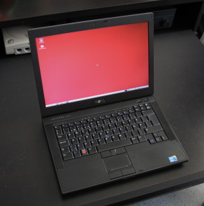
E6410 ja 64-bittinen Mint/Mate
Edit: No eihän ainakaan tässä E6410:ssä edes ole Bluetoothia, joten toimivuutta on sikäli vaikea arvioida.
Edit2: Telakkaa pikaisesti testattu. Voi lykästä koneeseen ihan lennossa ilman mitään komplikaatioita. USB-portit toimivat hyvin ja näyttökin tunnistui display portista oitis. Näytöt ja alapalkit eivät aina sijoitu ihan loogisesti, mutta kyllä ne toimimaan saa pienellä näpläämisellä. Maten alapalkkia voi raahata näytöltä toiselle alt pohjassa.
August 29th, 2015
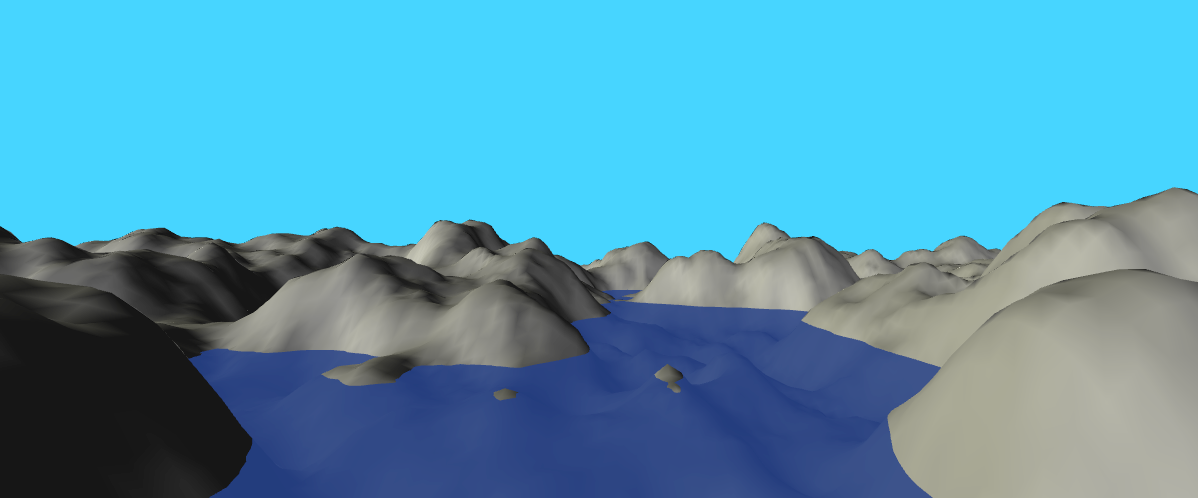
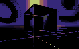
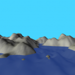
Skrollin tämän vuoden ensimmäinen numero ilmestyi juuri, ja mukana on taas omaakin tekstiäni: Maisemia Perlin-kohinalla. Kuten nimikin vihjaa, artikkelissa tehdään Processingilla pieni reaaliaikainen 3D-maasto käyttäen Perlin-kohinaa muodon laskentaan. Teron piirtämä takakannen PETSCII-kuva on sekin tutulla edikalla tehty.

March 18th, 2015
Virittelin jo aiemmin kasaan Joyduino-projektin, jolla sai emuloitua Atari-joystickiä PC:n näppäimistöltä. Projektissa oli kuitenkin kaksi ongelmaa: kolvaamista vaativa tarpeettoman mutkikas piirikortti ja hieman epämääräinen sarjaportin käsittely omalla ohjelmalla. Kuulin vasta myöhemmin, että Arduinon pinnit saa suljettua laittamalla ne input-moodiin, mikä teki kytkinpiirit tarpeettomiksi. Eli kun virtuaalisen joikkarin kytkintä ei paineta, pinni on sisääntulona ja kun painetaan, niin pinni vaihdetaan ulostuloksi ja laitetaan nollaan. Tältä pohjalta riitti tehdä triviaali johto D9-naarasliittimestä piikkirimaan, joka menee Arduinon headerin pinneihin 8..GND (ylös, nappi, alas, vasen, nappi 2, oikea, maa). Tulitusnappi 2 tässä MSX:n mukainen – muissa laitteissa saattaa olla eri piikissä. Oman C-ohjelman sijasta tein isäntäohjelman tällä kertaa Processingilla, niin se toimii saman tien useilla alustoilla. Arduinoon pitää ensin ladata Firmata, jotta Processing toimii sen kanssa. Firmata ei ole järin nopea, sillä aikaa haaskaantuu yksittäisten pinnien erikseen kääntelyyn ja protokollaan, mutta tässä tapauksessa nopeus oli ihan hyväksyttävä. Omaa, luultavasti pahempaa lägiään tulee Processingin päivitystaajuudesta, mutta sekään ei ollut vielä liikaa. Esimerkki täällä:
http://www.kameli.net/~marq/kode/joikkari.pde
Firmatan lisäksi tarvii asentaa Arduino-tuki Processingille, joten mikään avaimet käteen -ratkaisu tästäkään ei tullut. MSX:n kakkosnapin vahingossa sohimisesta voi seurata ongelmia joillakin koneilla – pinniä saatetaan käyttää muihin tarkoituksiin, joten joikkaportin pinniin 7 ei yleensä kannata kytkeä mitään. Toinen detsku on, että pelikone kannattaa käynnistää tai johto kytkeä vasta ohjelman herättyä, sillä muuten porttiin tulee ei-toivottuja painalluksia. Näppikseltä pelaaminen on jo kohtuullisen hyödyllistä, jos ehjää Atari-joystickiä ei satu olemaan, mutta vielä hyödyllisempi tämä viritelmä olisi vaikkapa joypadin kanssa. Katsotaan, iskeekö inspiraatio sellaisenkin tukemiseen jossain vaiheessa.
edit: Nappi 2 ja vasen menevät tosiaan ristiin piuhassa, koska huomasin vasta jälkikäteen, että MSX:ssä kakkosnappi onkin eri pinnissä. Helppo muuttaa koodista (ja muutenkin järjestys on aika satunnainen).
edit2: Äh, menköön. Tässä se joypad-tuki. Nappien ja kontrollerin nimeä joutunee vaihtamaan, mutta muuten toiminee suorilta: http://www.kameli.net/~marq/kode/joikkari2.pde
December 9th, 2013
Welcome to the PETSCII page, where you can find out everything you ever wanted to know about the crossplatform PETSCII editor ingeniously called PETSCII. The tool lets you create character-based screens and animations for the Commodore 64, VIC-20, PET and Plus/4 computers. Enjoy!
News
- 3.11.2024: Plenty of various PETSCII works at Zoo 2024. Also check out Ventti’s expanded version of the editor!
- 11.8.2024: Pågadata PETSCIIS available
- 11.2.2024: Fjälldata PETSCIIs right here
- 10.10.2023: DART 1.2 released with support for creating dirart from .c and .pet files
- 28.9.2023: The editor turned 10 years old. There’s even cake!
- 29.7.2023: Vammala Party PETSCIIs here
- 3.6.2023: X PETSCII entries are starting to appear here
- 12.2.2023: Quality PETSCII art at Fjälldata.
- 31.10.2022: The page got a little update with clearer, up to date instructions.
Usage
It should be straightforward to download and unzip the package (see downloads below), after which you can run the version that corresponds to your operating system of choice: Linux, Mac or Windows. 32-bit binaries are still included, but you may encounter problems with old Windows or Mac OS versions – I can’t support and test each and every one of them.
Use the GUI buttons for saving your work. The native file format is a C array, which is why the file extension should be “.c”. In addition, the automatic backup will create a file called _backup_.c in the program directory every two minutes or so. The Ref. button will load a reference image (png/jpg/gif) that can either be overlaid with the characters or converted to PETSCII.
For showing the piece on a real machine you need to export the picture to a .prg file. At the moment animations can’t be exported as standalone executables. See the keyboard shortcuts below, and in the case of source code exports check the generated file for further instructions. Not all the export options are available for all the target platforms. Optionally, create a d64 image (c1541 is part of VICE):
c1541 -format mypic,0 d64 mypic.d64 -attach mypic.d64 -write image.prg image
There’s also a video tutorial on the basic functions of the editor. See here: https://www.scenesat.com/videoarchive/250b4ced-b90e-11ea-b68e-00505685775e?t=55337
Mouse Buttons
- left mouse button – draw, select pen color, select char from the selector
- middle mouse button – char picker, select border color from the selector
- right mouse button – eraser, select bg color from the selector, lock/unlock frame on timeline, toggle lowercase on char selector
- mouse wheel – darken or lighten the shade on the Plus/4
Editing Commands
- C – convert colors to Plus/4 after loading a C64 image (Plus/4 only, not necessary with recent files any more)
- enter – switch to typing mode, shift-enter for inverted chars
- Alt (+shift) will let you type graphic characters like on a real machine
- Color selection and reverse, likewise
- Ins/Del/Backspace/PageUp/Dn/Home/End work
- Window managers etc. might reserve some key combinations for their own purposes, so beware
- esc – exit from typing mode, remove selection
- f – floodfill (keep it pressed and click), shift-f fills color only
- h – smart horizontal flip, shift-h at cursor
- r – smart rotate clockwise, shift-r at cursor
- space – toggle selection on/off
- T – convert the reference image to PETSCII – set a suitable background color yourself first. If the reference image has changed, it’ll be reloaded.
- tab – walk through predefined sets of related characters
- u – undo
- U – redo
- up/down arrow – grow and shrink stick characters
- v – smart vertical flip, shift-v at cursor
- x – invert, shift-x inverts at cursor
- +/- – shift horizontal and vertical stick character one step up/down or right/left
- ,/. – cycle through bg and border colors
- § – pick character+color (same as mmb), shift-§ (° or ½) to pick color only
GUI Toggles
- c – toggle crosshair
- g – toggle grid
- i – toggle info display
- t – cycle through different levels of reference image transparency
Animation Related
- 1..0 – jump to frame 1..10
- d – duplicate frame to the left
- end – jump to last frame
- home – jump to first frame
- l – lock/unlock frame from editing
- left/right – jump one frame
Modifier Keys
- alt – 1/4 char pixel drawing mode (keep alt pressed)
- ctrl (command on Macs) – selection mode: drag with lmb pressed to select a region, rmb to select free-form areas, ctrl-a selects the whole image
- shift (left) – coloring mode, only the color is replaced (keep shift pressed)
- shift (right) – character-only mode
File Operations
- a – export file as asm data
- A – export file as self-contained asm viewer (ACME format)
- b – export as self-contained BASIC viewer
- e – export a self-contained PRG that can be run directly
- E – export a .pet file
- p – export all frames as PNG images, shift-p includes borders. Note that the clickable button only exports the current frame with borders.
- q – export as SEQ (C-64 only)
- s – save (plain C data, the default image format)
- S – export as self-contained C viewer (cc65 format)
Cheat Sheet
Forgot some keys? Of course you did – even I don’t remember them all. Print out this handy cheat sheet to support your failing memory:
On Macs use the Command key instead of Ctrl.
Settings
You can control some general settings with a file called prefs.txt which should be in the same directory as the actual program. So far the following settings are recognized:
- ZOOM – editor pixel size. 2 by default. 1 is the minimum and anything beyond 3 might be rather unusable.
- FRAMERATE – update rate. 60 fps by default. Decrement for less CPU use, increment for better responsiveness. Going above the screen refresh rate might be impossible depending on the platform and system settings.
- MACHINE – one of C64, VIC20, PET, PETHI, PLUS4, DIRART. Leave empty to get the normal selector at start.
- ASPECT – aspect ratio on the machines where it counts. One of PAL/NTSC/SQUARE. If not set, default to PAL.
- PATH – default path for your images. Give a full path like /home/marq/Pictures. No quotation marks.
- BACKUPFILE – the name and optionally the full path of the backup file. If empty, defaults to the application folder and _backup_.c
- OFFSET – 0 or 1 to show canvas memory offsets.
- XSIZE and YSIZE – set a nonstandard canvas size.
- UNDODEPTH – Increase or decrease the amount of undo steps, 32 by default.
- TABLET – 1 to use the experimental tablet mode which makes it easier to click UI buttons when using a touchscreen. 0 for normal operation (default).
- FORCEMETAL – 1 to revert to the Metal UI style regardless of the platform default
- AWTSELECTOR – 1 to use AWT’s fileselector, 0 to use Swing. Leave empty to use the platform-specific default.
- DISABLEWHEEL – 1 to disable mouse wheel functionality in case it bugs you
- CONVERTER – command to run when exporting multiple frames (mostly meant for animated gifs). With ImageMagick use something like this: convert -delay 20 -loop 0 -scale 200%
Assign a new value like this: ZOOM=2. Note that on recent versions of macOS the prefs file might need to be in your home folder, e.g. /Users/marq.
There are some simple command line parameters as well. The parameters override prefs.txt.
- -c64, -vic20, -pet and so on will let you skip the initial dialog
- -zoom x sets, eh, the zoom
- -size x y for non-standard canvas sizes
Protips
- The selection can be used in several ways: it can be rotated, flipped, or even used for coloring regions (try pressing shift).
- Rotation, flipping, inverting etc. affect the character under the cursor when shift is pressed.
- The image -> PETSCII conversion depends on the selected background color, so experiment with multiple options. Three grayscale levels in the source image with bg color set as middle gray seems to work pretty well for photos.
- As of the latest versions, you can make converting much faster and iterative, as the reference image is reloaded if its timestamp has changed.
- You can reconvert existing images back to PETSCII as long as the palette is close enough and the dimensions match (320×200 and no borders for C64).
- PETSCII uses these C64 color values by Pepto, so do the same when working with external programs to ensure a faithful conversion. See m_c64.pde, m_vic20.pde and m_plus4.pde for the RGB values.
- Shift-mmb will pick just the color instead of character+color
- Select a pen color and ctrl-click another color on the selector to remap all the chars of the same color. If there’s a selection, only it will be affected.
- You can delete chars from a selection by clicking the char selector. It’ll leave you holes that don’t affect drawing – useful for example for cutting out “sprites”.
- Want to make animated gifs? Install ImageMagick command line tools, export as png (press p or P) and then simply:
convert -resize 200% -loop 0 -delay 10 frames*.png animation.gif
- There are only a few flicker colors that are steady in large quantities. Don’t use a flicker color for the border or even the bg, small details work better.
- For making some actual use of the dirart mode, try DART.
Troubleshooting
Trying to create a reliable crossplatform application in Java is tricky business these days. If all else fails I recommend downloading the source-only version and running it straight from Processing version 3.x. Bug reports can be sent to marq [at] iki [dot] fi or alternatively on CSDb.
- Apple’s so-called security won’t let you run unsigned apps. To make a long story short: go to System Preferences – Security & Privacy and allow apps downloaded from anywhere to run.
- Middle mouse button might not work on all Macs. Use the § key instead to pick a character from the canvas, if your keyboard has one. Border color can be selected by pressing the dot key.
- With all these Mac woes (and there’s probably more to come) you migth even consider running the editor inside a Linux/Windows virtual machine.
- Can’t draw and there’s an asterisk (*) next to the frame number? You’ve locked the frame. Press l or right click on the thumbnail (if any).
- File selector bugs – try setting AWTSELECTOR to 0 or 1. 0 will possibly fix a crashing bug on Linux.
- Some recent Ubuntu-based distros might complain that they Failed to load module “canberra-gtk-module”. The warning appears to be harmless, but if it bugs you, install the missing package libcanberra-gtk-module using apt or whatever package manager you prefer.
- Missed mouse clicks with Lenovo TrackPoint or mouse pad? Try fiddling with the typing delay/sensitivity setting.
Download
The compiled binaries + stable source are available right here: http://www.kameli.net/~marq/kode/petscii.zip. Note that you need to have the Java Runtime Environment installed on your system. I’m using JRE 1.8 (Java 8) myself, so that’s probably your safest bet. The tried and tested 2019 (Processing 2) version, not yet much worse featurewise, is still available here for a while in case you have trouble with the latest one or only have an old version of the JRE available.
WIP source-only release for the adventurous: http://www.kameli.net/~marq/kode/petscii-beta.zip or svn://kameli.net/marq/petscii. Revision 872 in the SVN repository is the last one that works on Processing 2. The code can be used according to the terms of the liberal WTFPL license.
Gallery
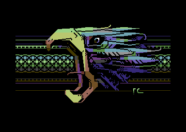
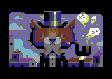
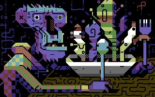
Some artistic endeavours to give you a glimpse of what’s possible.
-

-
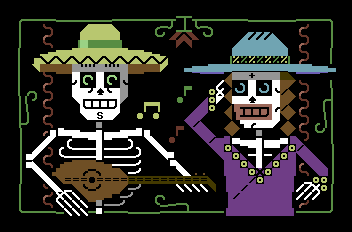
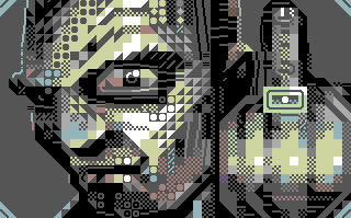
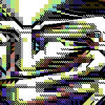
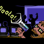
Marq: Whom Are You Going to Call?
-
-
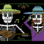
Marq: Calaveritas
-
-
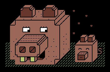
Marq: Posandeerit
-
-
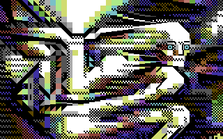
Dr. TerrorZ: PETSCII Tracing
-

-
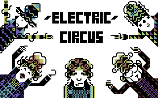
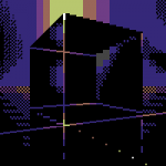
Dr. TerrorZ: Electric Circus
-
-
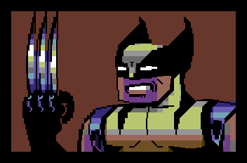
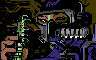
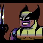
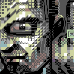
Dr. TerrorZ: Wolverine
-
-
Rexbeng: Undo
-
-
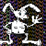
Manu: Rabbit on Acid Trip
-
-
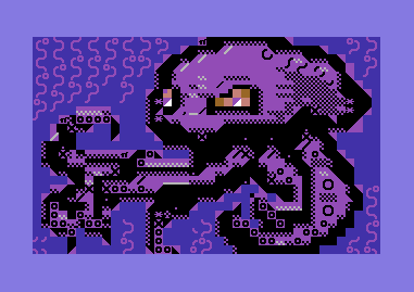
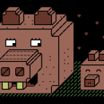
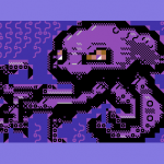
Manu: Octodore
-
-
Archmage: N00NEFUKWITEN0NE
-
-
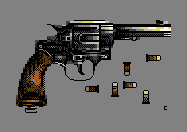
Electric: SixShots
-
-
Electric: Coltrane
-
-
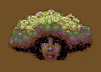
Electric: Hairy
-
-
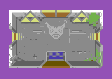
Awsm: Zelda PETSCII
-
-
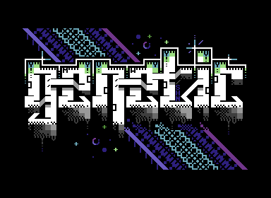
Shine: Genetic DNA
-
-
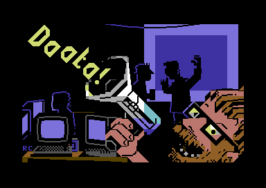
Redcrab: It Ain’t Pretty!
-
-
Redcrab: Datagubbe
-
-
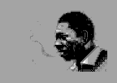
Redcrab: Ernie
-
-
iLKke: The Game Is Apaw!
-
-
iLKke: Breakfast of Champions
In addition to still images there are demos and games where the editor has been put into good use.
- 2 Fingers, Advanced Pet Dragons, Fort Django, Digiloi, Nine Rings, Petmanbatman and The Last Z-8 by Dr. TerrorZ
- Abre los ojos, Bionary, Ignition, Party Bus, Pets at Zoo, Thermonuclear War and We Are Computers by oobc
- Aerial Core, Smoke on the C64 and Skybox by Extend
- Aerodementic and Pikku Kuusnelonen by Wrenchotron
- Alien Finale by Proxima
- Alien Trailer, Sliced Blue, Awakening Computer – Alien Opening Scene, Broken Record, Petscroll, What Is Special Order #937?, Halloween the 40th Anniversary Celebration Demo, Space Invaders, The Crack in the Cosmic Egg, H.E.R.O. Animated PETSCII Loading Screen, Zeroid Bounce, Cowboynessness and Hokuto Forcer by Hokuto Force
- Beisikki demo, C-visa 2016, The First Ball, Rock joka tiesi… liikaa!, Nothing but PET SKI and Cosmic Bakery by Fit (& Friends)
- Feelgood and Innerverse by Gorbat Soft
- Je t’aime mon monstre and Lovecats by Atlantis
- Megapetscii by Hackers
- MerryXmas and Nothing But PETSCII by Genesis Project
- On Fire Intro by Fairlight
- PETSCII Intro by Atlantis and F4CG
- PETSCII Reader for Sinclair Spectrum by Carlosanta
- Shareware by Dekadence
- Shine Logo Collection II by Arsenic & Delysid
- Shock by Electric & Vent
- Star Wars PETSCII by Debris & Deetsay
- Tales of Edoras and Lycan by The Solution
Additions and corrections most welcome, as usual.
Acknowledgements
Thanks to Dr. TerrorZ for his artworks, numerous comments and remap tables, Viznut for help with the VIC-20, Six for the SEQ conversion example, BassCadet for bug reports, Groepaz and Deekay for help with dirart, and Rexbeng, Manu, Shine, Electric, Archmage, Hammerfist, Awsm, Redcrab and iLKke for gallery images.
October 2nd, 2013
Perjantai-illan hätäinen pikku Processing-projekti rupesi paisumaan ja alkaa olla jo hiljalleen ihan käyttökelpoinen. Tarkoituksena oli tehdä Zoo 2013:n PETSCII-kilpailua varten minimalistinen editori, jolla saisi lätkittyä ruudulle merkkejä väreineen ja sitten näytettyä niitä oikealla kuusnelosella. Mitään kunnollista ei tuntunut löytyvän valmiina Linuxille tai Mäkille, joten tehdään sitten itse. “Feature creep” iski pahasti päälle ja tein yhtä sun toista lisäystä. Tällä hetkellä ohjelma osaa jo seuraavaa:
- Piirto, kumitus ja väritys
- Reunuksen ja taustavärin vaihto
- Merkin poiminta
- Kuvien lataus ja tallennus
- Kuvien eksporttaus C-, assembler- ja BASIC-muotoon
- Simppeli pikselipiirtomoodi 1/4-merkeillä
- Alueen valinta ja kopiointi/tyhjennys
- PETSCII:n uudelleenjärjestely helpompaan muotoon
- Esikatselu venähtäneillä merkeillä ilman gridiä
Katsotaan, kuinka pitkälle into vielä riittää. Kaikenlaista muutakin mahdollista voisi lisäillä loputtomasti, mutta ainakin undo olisi varsin tarpeellinen toiminto. Animaatiota on pyydetty myös, mutta katsotaan nyt. Siinä vaiheessa, kun into loppuu, niin kintaat putoavat välittömästi 🙂
edit: Niin, jäi linkit laittamatta:
edit2: Tukee nyt myös VIC-20:tä.
edit3: Dokumentaatiota nyt täällä: http://www.kameli.net/marq/?page_id=2717
September 29th, 2013
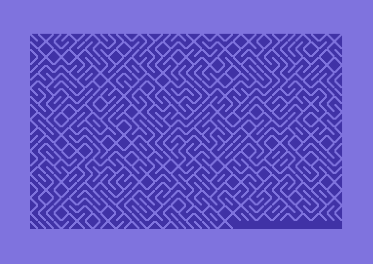
Ohjelmistotutkimus (software studies) on verrattain uusi tulokas kulttuurintutkimuksen kentällä. MIT Pressin kirjasarjassa on aiheesta julkaistu jo muutama teos, joista viimeisin on 10 PRINT, tai koko komeudessaan:
10 PRINT CHR$(205.5+RND(1)); : GOTO 10
Koodinpätkän voi kukin kirjoitella Commodore 64:äänsä tai VIC-20:een, ja lopputuloksena pitäisi tulla labyrinttiä muistuttava mutkikas kuvio (ks. lopussa oleva kuva). Lyhykäisesti selitettynä ohjelma tulostaa satunnaisesti joko merkin 205 (kenoviiva) tai 206 (kauttaviiva), joiden interaktiosta syntyy loputtomasti enemmän ja vähemmän aitoja sokkeloita.
Kirja käsitteleekin aihetta sitten kaikkea muuta kuin lyhykäisesti – kansien väliin on saatu 309 sivua erilaisia variantteja ja sivupolkuja. Kirjoittajia on peräti kymmenen ja joukossa joitakin tuttujakin nimiä, kuten monessa tekniikan historian liemessä marinoidut Nick Montfort ja Ian Bogost, sekä Processingin toinen isä Casey Reas. Teosta on työstetty yhteisvoimin Wikissä, joten yksittäisen kirjoittajan panosta on mahdoton arvioida erikseen. Moderniin tyyliin koko kirja on myös ladattavissa pdf-muodossa verkosta sen kotisivuilta.
Lyhyeltä vaikuttavasta ohjelmanpätkästä singotaan moneen suuntaan, kuten labyrintteihin, ruudukon käyttöön kuvataiteessa, satunnaislukuihin, Commodoreen ja BASIC-ohjelmoinnin historiaan, mikä osoittaa ainakin sen, kuinka monimutkaisia kulttuuriset kytkökset ovat. Paljon sivuja on uhrattu onelinerin erilaisille varianteille ja muille alustoille tehdyille porttauksille. Milloin muunnellaan merkkien satunnaisuutta, milloin käytetään eri merkkejä tai toteutetaan samanlainen ohjelma jollakin aivan toisella alustalla, kuten Atari 2600:lla. Jokaisen sivupolun kautta päästään kertomaan jotain uutta laitteista, ohjelmointikielistä ja algoritmeista. Loppupuolella on hieman puuduttavan puolelle venähtänyt luku, jossa pitkien BASIC-esimerkkien kautta ratkotaan sokkelon ohjelmallista läpikäyntiä.
Välillä tuntui siltä, että onpas tässä keksitty nokkela punainen lanka, joka sitoo yhteen monia erilaisia teemoja – välillä taas siltä, että on ollut pakko tehdä tikusta asiaa, kun yhden rivin BASIC-pätkä ei ole kuitenkaan kantanut ihan kolmensadan sivun verran. Ehkä parasta antia itselleni olivat viittaukset taidehistoriaan ja satunnaislukujen merkityksen käsittely. Teknistä ymmärrystä tarvitaan melko paljon, jos kirjan teemoja aikoo oikeasti ymmärtää, vaikka toisaalta tuntuikin siltä, että joissakin yksityiskohdissa on popularisoinnin hengessä oikaistu hieman liikaakin. Summa summarum: mielenkiintoinen avaus, jonka kautta voi hahmottaa ainakin 1980-lukulaista ajattelua; aikaa, jolloin ohjelmointi tuli koteihin ja oli vielä luonteva käyttökohde tietokoneelle.

April 15th, 2013
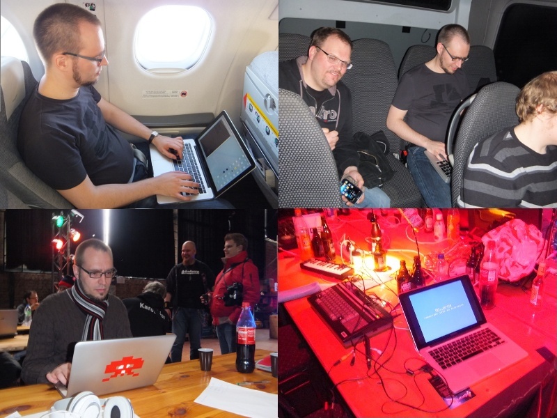
Pääsiäisen viihteestä vastasi Revision 2013 Saksan Saarbrückenissä. Revision on käytännössä viimeinen iso kansainvälinen demoparty The Partyn lerpahdettua ja Assemblyn sekä The Gatheringin muututtua pikemminkin pelitapahtumiksi. Aiemmin party tunnettiin nimellä Breakpoint. Noin kauas ei viitsinyt lähteä ilman mitään omaa tuotosta, joten edellisenä iltana, lentokoneessa, bussissa, hotellilla sekä partypaikan aulassa koodattiin ankarasti deadlineen saakka ja hiukan sen ylikin. Lopputuloksena syntyi pitkästä aikaa MSX:lle demo, VJ-henkinen Amurisus. Youtube, Pouet ja msx.orgin hieman apologeettinen uutinen aiheesta.
Tein ensimmäiset MSX-produni vuonna 1997, jolloin työkalut olivat vielä primitiivisiä. Koskaan en ole koodannut itse MSX:llä, vaan heti alusta asti oli käytössä TASM-niminen assembler MS-DOS:n alla. Aivan alussa rämppäsin korppua PC:stä MSX:lle testausta varten, mutta aika nopeasti koko kehitys siirtyi PC-pohjaiseksi, kun fMSX-emulaattori alkoi olla varteenotettava vaihtoehto oikealle koneelle. Edelleenkään ei olla siinä tilanteessa, etteikö lopulta olisi pakko testata myös aidolla koneella, koska etenkin MSX1:n videopiiri on jonkin verran arvaamaton, kun liikutaan sen suorituskyvyn rajoilla. Vuoteen 2008 asti käytössä oli Yzin assemblerilla kirjoittama musiikkirutiini, jossa säveltäminen tapahtui nuotteja käsin datalauseisiin kirjoittamalla.
Tätä nykyä puhtaalla asmilla kirjoittelu olisi jo hieman tuskallisen puolella, vaikka Z80 onkin ykkösnimi perinteisten kasibittisten prosujen joukossa. Onneksi työkalut ovat kehittyneet oleellisesti, joten pääosa koodauksesta tuli tällä erää tehtyä ihan C-kielellä SDCC:n avustamana. Sekaan saa aikakriittisiä osia varten helposti inline-assembleria, joten paljon parempaa yhdistelmää ei voisi juuri toivoa. Ammoisten bat-viritysten sijasta käytössä on kunnollinen Makefile, joka kääntää tarvittavat osat, rakentaa emulaattorille levytiedoston ja käynnistää demon joko OpenMSX:ssä tai Nowindin yli oikealla koneella. Amurisusia tehdessä käytimme ensimmäistä kertaa versionhallintaa: lähdekoodi oli Tampereella sijaitsevassa Subversion-palvelimessa (itse istuimme Saksassa pöydän eri puolilla), mikä säästi reilusti aikaa ja vaivaa jopa näin pienessä projektissa, kun kahden koodarin rinnakkaiset muokkaukset sai yhdistettyä ilman eri sählinkiä. Sivutuotteena syntyi vielä varmuuskopio lähdekoodista. Musiikin sävellykseen on nykyään tekstieditoria helpompia tapoja, etunenässä alun perin Amstrad CPC:tä varten tehty Arkos Tracker. Kasibittikoodauksessa tarpeelliset kuvakonvertterit ja esilaskennat tein Processingilla, mikä säästää sekin vaivaa aiempaan C-kielellä näpyttelyyn verrattuna.
Lopputuloksesta tuli sunnuntain pikku viilailujen jälkeen varsin tyydyttävä. Mitään teknisesti mullistavaa tuossa ajassa ei olisi ehtinyt tehdäkään, mutta onneksi konsepti kantoi ja musasynkka toi ryhtiä muuten sekalaiseen sisältöön. Sijoitus jäi kilpailussa vaatimattomaksi, sillä taso oli varsin kova ja muut produt ilmeisen työllä ja tuskalla väännettyjä. Nykyään demoja tulee tehtyä joka tapauksessa omaksi huviksi, eikä palkinnoilla tai sijoituksella ole enää sanottavaa merkitystä – saatiinpahan kikkare harrastuneen yleisön nähtäväksi. MSX-yhteisöön tällainen happoinen kokeilu ei luultavasti vetoa, sillä demoja tuntevienkin tyyppien viitekehys on yleensä tukevasti 1990-luvun alkupuolen nostalgisissa MSX2-tekeleissä.
April 1st, 2013
Next Posts
Previous Posts